Saturday, December 27, 2008

QOS pre-classify


When packets pass through a VPN, the original IP header is encapsulated. For eg, in case of GRE tunnel, GRE is the encapsulation protocol and IP becomes the passenger protocol, ofcourse using IP again as the transport protocol.

Original Packet

IP
TCP
Data


After entering the VPN tunnel

New IP Header
Encrypted Original Packet


However Cisco IOS has a feature, in which it copies the TOS byte of the original IP header to new IP Header. This is good, because intermediate nodes can examine the TOS byte for classification purpose, but are unable to use a multifield classifer, which examines more than just the TOS byte for classifcation purposes.


Qos Preclassify, allows the router which starts the encapsulation and encryption to examine more than the TOS byte. With the Qos Preclassify, it stores headers of the original packet before encapsulation and encrytion in memory. This helps in classifying based on multi field classifiers.

Copied directly from http://www.cisco.com/en/US/tech/tk543/tk545/technologies_tech_note09186a008017405e.shtml
----------------------------------------------------

Where Do I Apply the Service Policy?

You can apply a service policy to either the tunnel interface or to the underlying physical interface. The decision of where to apply the policy depends on the QoS objectives. It also depends on which header you need to use for classification.

  • Apply the policy to the tunnel interface without qos-preclassify when you want to classify packets based on the pre-tunnel header.

  • Apply the policy to the physical interface without qos-preclassify when you want to classify packets based on the post-tunnel header. In addition, apply the policy to the physical interface when you want to shape or police all traffic belonging to a tunnel, and the physical interface supports several tunnels.

  • Apply the policy to a physical interface and enable qos-preclassify on a tunnel interface when you want to classify packets based on the pre-tunnel header.

----------------------------------------------------

Lets verify the usage of qos-preclassify in as mentioned above with out example topology below


3640a

class-map match-all TELNET
match access-group 102
!
!
policy-map telnetmap
class TELNET

interface Tunnel0
ip address 11.0.0.2 255.255.255.0
load-interval 30
tunnel source Ethernet0/0
tunnel destination 192.168.1.18

interface Ethernet0/0
ip address 192.168.1.17 255.255.255.0
half-duplex


ip route 12.0.0.1 255.255.255.255 11.0.0.1
access-list 102 permit tcp any host 12.0.0.1 eq telnet
2610xm


interface Loopback0
ip address 12.0.0.1 255.255.255.255
!
interface Tunnel0
ip address 11.0.0.1 255.255.255.0
tunnel source FastEthernet0/0
tunnel destination 192.168.1.17
!
interface FastEthernet0/0
ip address 192.168.1.18 255.255.255.0
duplex auto
speed auto

line vty 0 4
password telnet
login


Case 1)
Apply the policy to the tunnel interface without qos-preclassify when you want to classify packets based on the pre-tunnel header.

Our match statement above is multi field classifier in class-map TELNET , it has to examine more than the TOS byte to classify packets based on the access-group 102.

3640a(config)#int tunnel 0
3640a(config-if)#service-policy output telnetmap
3640a(config-if)#^Z

--Generate telnet traffic

3640a#telnet 12.0.0.1
Trying 12.0.0.1 ... Open


User Access Verification

Password:
2610XM>exit

[Connection to 12.0.0.1 closed by foreign host]
3640a#show policy-map int tunnel 0
Tunnel0

Service-policy output: telnetmap

Class-map: TELNET (match-all)
30 packets, 1255 bytes
30 second offered rate 0 bps
Match: access-group 102

Class-map: class-default (match-any)
0 packets, 0 bytes
30 second offered rate 0 bps, drop rate 0 bps
Match: any
3640a#


By applying the policy-map to the tunnel interface and generating the telnet traffic to 2610xm, we can see that it classifies packets based on our class-map TELNET rather than class-default, which means the tunnel interface is able to read the pre-tunnel header to perform a multi field classification.


Case 2)
Apply the policy to the physical interface without qos-preclassify when you want to classify packets based on the post-tunnel header.

Now we need to apply the service-policy command to the physical interface (remove from the tunnel interface) and it should only be able to the see the post-tunnel header, unable to classify packets based on
class-map TELNET. Make sure you issue a clear counters to get a clean slate when using show policy-map int command

3640a(config)#int e0/0
3640a(config-if)#service-policy output telnetmap
3640a(config-if)#

--Generate telnet traffic

3640a#telnet 12.0.0.1
Trying 12.0.0.1 ... Open


User Access Verification

Password:
2610XM>exit

[Connection to 12.0.0.1 closed by foreign host]
3640a#
3640a#show policy-map int e0/0
Ethernet0/0

Service-policy output: telnetmap

Class-map: TELNET (match-all)
0 packets, 0 bytes
5 minute offered rate 0 bps
Match: access-group 102

Class-map: class-default (match-any)
26 packets, 2040 bytes
5 minute offered rate 1000 bps, drop rate 0 bps
Match: any
3640a#

As seen, it could not classify packets because the original IP header has been encapsulated, hence all traffic (telnet) matched the class-default.


3)
Apply the policy to a physical interface and enable qos-preclassify on a tunnel interface when you want to classify packets based on the pre-tunnel header.
Below will be the output of the show policy-map interface, after adding qos-preclassify to the tunnel interface.

3640a#sh policy-map int e0/0
Ethernet0/0

Service-policy output: telnetmap

Class-map: TELNET (match-all)
24 packets, 1920 bytes
5 minute offered rate 0 bps
Match: access-group 102

Class-map: class-default (match-any)
3 packets, 180 bytes
5 minute offered rate 0 bps, drop rate 0 bps
Match: any
3640a#

As said, it could successfully classify based on class-map TELNET.

Wednesday, December 24, 2008

IP NAT OUTSIDE


Requirements
1) R1 only accepts connections from 172.30.1.0/24 network
2) R2 sees R1 only as 192.168.1.0/24 node (i.e 192.168.1.200)


First starting with basic interface configs

R2#sh run int f0/23
Building configuration...

Current configuration : 89 bytes
!
interface FastEthernet0/23
no switchport
ip address 192.168.1.104 255.255.255.0
end


R1#sh run int e0
Building configuration...

Current configuration : 88 bytes
!
interface Ethernet0
ip address 172.30.1.2 255.255.255.0
ip access-group 101 in
end
access-list 101 permit ip 172.30.1.0 0.0.0.255 any


NAT_ROUTER#sh run int e0/0
Building configuration...

interface Ethernet0/0
description connection to R1
ip address 172.30.1.1 255.255.255.0
ip nat inside
ip virtual-reassembly
half-duplex
end


interface Ethernet0/1
description connection to R2
ip address 192.168.1.100 255.255.255.0
ip nat outside
ip virtual-reassembly
half-duplex
end

ip nat inside source static 172.30.1.2 192.168.1.200


As you would already noticed R2, is a Cat 3550 switch. We have finished designating the nat inside and outside interfaces. Also notice the access-list 101 on R1 E0 interface permitting only connections from 172.30.1.0/24 subnet. Also notice the static translation 172.30.1.2 ----> 192.168.1.200

Lets verify connection from R2 to R1

R2#ping 192.168.1.200

Type escape sequence to abort.
Sending 5, 100-byte ICMP Echos to 192.168.1.200, timeout is 2 seconds:
.....
Success rate is 0 percent (0/5)
R2#

*Mar 1 03:14:34.587: ICMP: dst (172.30.1.2) administratively prohibited unreachable sent to 192.168.1.104
R1#
*Mar 1 03:14:36.587: ICMP: dst (172.30.1.2) administratively prohibited unreachable sent to 192.168.1.104
R1#
*Mar 1 03:14:38.587: ICMP: dst (172.30.1.2) administratively prohibited unreachable sent to 192.168.1.104
R1#
*Mar 1 03:14:40.587: ICMP: dst (172.30.1.2) administratively prohibited unreachable sent to 192.168.1.104
R1#


Thats right R3 only accepts connections from 172.30.1.0/24 subnet. So lets add the ip nat outside statement on the nat router.

NAT_ROUTER(config)#access-list 102 permit ip 192.168.1.0 0.0.0.255 any
NAT_ROUTER(config)#ip nat pool poolout 172.30.1.3 172.30.1.254 netmask 255.255.255.0
NAT_ROUTER(config)#ip nat outside source list 102 pool poolout


Please note that when a source list, which specifies an access-list is used, the outside global address must be matched to an outside local pool, specified by pool keyword. Lets try the test again

R2#ping 192.168.1.200

Type escape sequence to abort.
Sending 5, 100-byte ICMP Echos to 192.168.1.200, timeout is 2 seconds:
.....
Success rate is 0 percent (0/5)
R2#


Well it's still not working! Let take a closer look at R1 and NAT_ROUTER

*Mar 1 03:21:06.143: ICMP: echo reply sent, src 172.30.1.2, dst 172.30.1.6
R1#
*Mar 1 03:21:08.143: ICMP: echo reply sent, src 172.30.1.2, dst 172.30.1.6
R1#
*Mar 1 03:21:10.143: ICMP: echo reply sent, src 172.30.1.2, dst 172.30.1.6
R1#
*Mar 1 03:21:12.143: ICMP: echo reply sent, src 172.30.1.2, dst 172.30.1.6
R1#
*Mar 1 03:21:14.143: ICMP: echo reply sent, src 172.30.1.2, dst 172.30.1.6
R1#

It seems like the NAT_ROUTER translated the outside global address (192.168.1.104) orginating from R2's f0/23 interface is mapped to an outside local address 172.30.1.6 and sent to R1. R1 did reply as indicated the debug ip icmp messages on R1. Obviously the echo reply has not reached R2. Let's examine the NAT_ROUTER

NAT_ROUTER#
*Mar 14 21:04:47.547: IP: tableid=0, s=172.30.1.2 (Ethernet0/0), d=172.30.1.6 (Ethernet0/0), routed via RIB
*Mar 14 21:04:47.551: IP: s=172.30.1.2 (Ethernet0/0), d=172.30.1.6 (Ethernet0/0), len 100, rcvd 3
*Mar 14 21:04:47.551: ICMP: echo reply rcvd, src 172.30.1.2, dst 172.30.1.6
NAT_ROUTER#
*Mar 14 21:04:49.547: IP: tableid=0, s=172.30.1.2 (Ethernet0/0), d=172.30.1.6 (Ethernet0/0), routed via RIB
*Mar 14 21:04:49.551: IP: s=172.30.1.2 (Ethernet0/0), d=172.30.1.6 (Ethernet0/0), len 100, rcvd 3
*Mar 14 21:04:49.551: ICMP: echo reply rcvd, src 172.30.1.2, dst 172.30.1.6


The NAT_ROUTER also shows it correctly forwarded the icmp echo reply from 172.30.1.2 (R1) to 172.30.1.6.

NAT_ROUTER#sh ip nat translations
Pro Inside global Inside local Outside local Outside global
--- --- --- 172.30.1.3 192.168.1.100
--- --- --- 172.30.1.6 192.168.1.104
--- 192.168.1.200 172.30.1.2 --- ---
NAT_ROUTER#

As seen from above command, there is a mapping from 172.30.1.6 --> 192.168.1.104 (R2's F0/23 int). However, the traffic was not routed to R2. This because the add-route keyword in the ip nat outside was not configured.

Let's make the change on NAT_ROUTER

NAT_ROUTER(config)#no ip nat outside source list 102 pool poolout
NAT_ROUTER(config)#ip nat outside source list 102 pool poolout add-route

Lets test connectivty from R2 again

R2#ping 192.168.1.200

Type escape sequence to abort.
Sending 5, 100-byte ICMP Echos to 192.168.1.200, timeout is 2 seconds:
!!!!!
Success rate is 100 percent (5/5), round-trip min/avg/max = 8/11/12 ms

So what did the add-route keyword on the NAT_ROUTER do. Well to answer the question, we need to examine the routing table on NAT_ROUTER

NAT_ROUTER#sh ip route
Codes: C - connected, S - static, R - RIP, M - mobile, B - BGP
D - EIGRP, EX - EIGRP external, O - OSPF, IA - OSPF inter area
N1 - OSPF NSSA external type 1, N2 - OSPF NSSA external type 2
E1 - OSPF external type 1, E2 - OSPF external type 2
i - IS-IS, su - IS-IS summary, L1 - IS-IS level-1, L2 - IS-IS level-2
ia - IS-IS inter area, * - candidate default, U - per-user static route
o - ODR, P - periodic downloaded static route

Gateway of last resort is 192.168.1.254 to network 0.0.0.0

172.30.0.0/16 is variably subnetted, 3 subnets, 2 masks
S 172.30.1.3/32 [1/0] via 192.168.1.104
C 172.30.1.0/24 is directly connected, Ethernet0/0
S 172.30.1.7/32 [1/0] via 192.168.1.100
C 192.168.1.0/24 is directly connected, Ethernet0/1
S* 0.0.0.0/0 [1/0] via 192.168.1.254

NAT_ROUTER#sh ip nat translations
Pro Inside global Inside local Outside local Outside global
--- --- --- 172.30.1.3 192.168.1.104
--- --- --- 172.30.1.7 192.168.1.100
--- 192.168.1.200 172.30.1.2 --- ---
NAT_ROUTER#

*The outside local --> Outside global mapping changed because we issued no ip nat pool statement in the previous, which cleared the translations. It has automatically added a host route pointing the outside local address to the outside global address, which was not present before.


Friday, December 19, 2008

Study Update

Well, at present I am reading Cisco QOS Exam certification guide. Previously, I had not bought Internet Routing Architectures, the definitive guide to BGP. I couldnt do without it, also I realised by reading that I am somewhere there to the SP track. Well, I guess I am getting ahead of myself here (havent even finished R&S and there he goes talking about SP). My love for MPLS and other service provider technologies is a hint to where I am heading. Hopefully the new year will bring something I always yearned for!

Saturday, November 29, 2008

MPLS VPN

MPLS (Multiprotocol Label Switching) offers Layer 3 VPN services by means of MPLS core provider network. MPLS VPNs make use of another MPLS application namely MPLS unicast IP routing in the MPLS backbone. For enabling an MPLS core backbone, all routers including PE must support LDP (Label Distribution Protocol) and CEF (Cisco Express forwarding).

The essential parts of MPLS VPN are
  • Provider Router (P) : A LSR (Label Switch Router) in the core of provider network, which does not have direct link to CE. It only forwards labelled packets and ignores customer VPN routes.
  • Provider Edge Router (PE) : A LSR, that has atleast one link to a CE router and associates each CE routes to appropriate routing tables. It will also be running a control plane protocol such MP-BGP to exchange CE routes with other PEs.
  • Customer Edge Router (CE): Edge router on customer site that has no knowledge of MPLS and directly connects to a MPLS PE.

MPLS VPN working can be summed up as follows
  • CEs exchange routes with PEs.
  • PEs in turn store CE routes into its own routing table (VRF)
  • PEs advertise CE routes to only other PEs in the MPLS cloud using MP-BGPs. MP-BGP allows the addition of an address family with a traditional BGP NLRI, which will discussed more in the detail later.

Some of the other key concepts, which needs to be covered are
  • VRFs (Virtual Routing and Forwarding tables)
  • RD (Route Distinguishers)
  • RT (Route Targets)

Virtual Routing and Forwarding tables (VRF)
Each customer must see only routes belonging to the customer. This is made possible by a VRF table on an MPLS aware router such as the PE. So, each customer is associated with a VRF on the PE to which it connects. Three components make the VRF table
  • An IP routing table
  • A CEF FIB, derived from the VRF RIB
  • An interface or group of interfaces associated with the VRF
  • A separate instance of the routing protocol (per VRF) used to exchange routes with CEs

Route Distinguishers (RD)
As mentioned before PEs make use of MP-BGP to advertise customer routes to other PEs in the MPLS cloud. A normal BGP NLRI (prefix) just consists of prefix. To differniate between overlapping prefixes (when multiple customers advertise the same prefix) , MPLS deals with this by adding another number before the traditional BGP NLRI, namely an address family. BGP/MPLS IP Virtual Private networks specifies an address family for supporting IPv4 MPLS VPNs called Route Distinguishers. The new NLRI format called a VPN-V4, has a 64-bit RD and a 32-bit IPv4 prefix.

Route Targets (RT)
When say PE1 advertises certain routes to PE2, it also advertises Route Targets as BGP extended community attributes. By associating a Route-Target with a particular a route advertisement, PE2 could dertermine into which VRF the associate route must go. As we'll see in the configuration examples later, each VRF has an export and import Route-Target statement. A simple pseudocode below would make this clearer

PE1
VRF definition for Customer A
export 10
import 10


PE2
VRF definition for Customer A
export 10
import 10

When PE1 advertises a route 10.3.3.0/24 from customer A to PE 2, it will associate a route target 10. PE2 seeing a route-target 10 with the prefix 10.3.3.0/24 and comparing the route-target value with its import statement in its definition of Customer As VRF places that particular prefix in customer As VRF.

Configuration Example

Keeping these concepts in mind, lets move onto the configuration details. I'd highly recommend reading more on MPLS VPN control plane and data plane, BGP and learning how to configure basic MPLS IP unicast forwarding.
Here comes the fun part. Take a look at the above topology and lets make list of what needs to be implemented. The dynagen file for the above topology is given below.

1) Configure Routing Protocols on the Customer Edge Routers (CE-A1 , CE-A2 , CE-B2 ,CE-B2)
2) Define VRFs on the PE Routers for the customers and associating VRF interfaces on the PE Routers (PE1 and PE2)
3) Configuring Routing protocols between PE routers and CE routers.
4) Configure the Provider Network
5) Verification


1) Configure Routing Protocols on the Customer Edge Routers
If you're reading how to configure MPLS VPNs, I can safely assume you already know this part. However, below is configuration example for one of the customer edge routers (CE-A2). RIP is the routing protocol run on the CEs

CE-A2#sh run | be rip
router rip
version 2
network 10.0.0.0
network 12.0.0.0
network 172.31.0.0
no auto-summary

2) Define VRFs on the PE Routers for the customers and associating VRF interfaces on the PE Routers (PE1 and PE2)

As mentioned before, VRFs need to be defined only on PEs. P routers have no idea of VRFs or customer routes, it simply forwards based on labels. CE-A1, CE-A2 are customer A sites and CE-B1, CE-B2 are customer B sites.


PE1

ip vrf customerA
rd 1.1.1.1:1
route-target export 1:100
route-target import 1:100
!
ip vrf customerB
rd 1.1.1.1:2
route-target export 2:200
route-target import 2:200

#Associate the interface that connects to customer A and customer B to the appropriate VRF

interface Ethernet0/0
ip vrf forwarding customerA
ip address 172.31.241.1 255.255.255.0
!
interface Ethernet0/1
ip vrf forwarding customerB
ip address 172.31.242.1 255.255.255.0
PE2

ip vrf customerA2
rd 3:200
route-target export 1:100
route-target import 1:100
!
ip vrf customerB2
rd 4:200
route-target export 2:200
route-target import 2:200

#Associate the interface that connects to customer A and customer B to the appropriate VRF

interface Ethernet0/0
ip vrf forwarding customerA2
ip address 172.31.243.1 255.255.255.0
!
interface Ethernet0/1
ip vrf forwarding customerB2
ip address 172.31.244.1 255.255.255.0


As seen from the above configuration, the VRF names for customer A is customerA on PE1 and customerA2 on PE2. This is done intentionally to show that customer VRF names are only locally significant. The routes exported from one PE and imported into another PE into a particular VRF definition solely relies on route-target values.

3) Configuring Routing protocols between PE routers and CE routers.


Now that VRFs have been defined for each customer, we can configure dynamic routing protocols between PE and CE routers. We go into the same RIP configuration (ignore the sections in green for now). Using the address-family ipv4 vrf command, we run dynamic routing protocols between PE and CE. Please note that RIP has already been configured on CEs in the first step.

PE1#sh run | be rip
router rip
version 2
network 192.168.1.0
no auto-summary
!
address-family ipv4 vrf customerB
network 172.31.0.0
no auto-summary
version 2
exit-address-family
!
address-family ipv4 vrf customerA
network 172.31.0.0
no auto-summary
version 2
exit-address-family
!

PE2#sh run | be rip
router rip
version 2
network 192.168.2.0
no auto-summary
!
address-family ipv4 vrf customerB2
network 172.31.0.0
no auto-summary
version 2
exit-address-family
!
address-family ipv4 vrf customerA2
network 172.31.0.0
no auto-summary
version 2
exit-address-family
!


Lets do some verification, we can indeed see the routes from CE-A1 on PE1 and CE-A2 on PE2.

PE1#sh ip route vrf customerA

Routing Table: customerA
Codes: C - connected, S - static, R - RIP, M - mobile, B - BGP
D - EIGRP, EX - EIGRP external, O - OSPF, IA - OSPF inter area
N1 - OSPF NSSA external type 1, N2 - OSPF NSSA external type 2
E1 - OSPF external type 1, E2 - OSPF external type 2
i - IS-IS, su - IS-IS summary, L1 - IS-IS level-1, L2 - IS-IS level-2
ia - IS-IS inter area, * - candidate default, U - per-user static route
o - ODR, P - periodic downloaded static route

Gateway of last resort is not set

172.31.0.0/24 is subnetted, 1 subnets
C 172.31.241.0 is directly connected, Ethernet0/0
182.2.0.0/24 is subnetted, 1 subnets
R 182.2.2.0 [120/1] via 172.31.241.2, 00:00:13, Ethernet0/0


PE2#sh ip route vrf customerA2

Routing Table: customerA2
Codes: C - connected, S - static, R - RIP, M - mobile, B - BGP
D - EIGRP, EX - EIGRP external, O - OSPF, IA - OSPF inter area
N1 - OSPF NSSA external type 1, N2 - OSPF NSSA external type 2
E1 - OSPF external type 1, E2 - OSPF external type 2
i - IS-IS, su - IS-IS summary, L1 - IS-IS level-1, L2 - IS-IS level-2
ia - IS-IS inter area, * - candidate default, U - per-user static route
o - ODR, P - periodic downloaded static route

Gateway of last resort is not set

172.31.0.0/24 is subnetted, 1 subnets
C 172.31.243.0 is directly connected, Ethernet0/0
10.0.0.0/24 is subnetted, 1 subnets
R 10.3.3.0 [120/1] via 172.31.243.2, 00:00:09, Ethernet0/0
12.0.0.0/24 is subnetted, 1 subnets
R 12.3.3.0 [120/1] via 172.31.243.2, 00:00:09, Ethernet0/0


At this point CE-A1 will not be able to reach CE-A2, similarly CE-B1 to CE-B2, as the provider network has not yet been fully configured.


4) Configure the Provider Network


This can be further broken down into 3 steps

i) Configure routing protocols in the Provider Core
ii) Configure MPLS in Provider Core
iii) Configure MP-BGP on PEs to exchange VRFs


i) Configure routing protocols in the Provider Core
Again this is a simple step. We'll be running RIP in the provider network.

PE1#sh run | be rip
router rip
version 2
network 192.168.1.0
no auto-summary

P1#sh run | be rip
router rip
version 2
network 192.168.1.0
network 192.168.2.0
no auto-summary

PE2#sh run | be rip
router rip
version 2
network 192.168.2.0
no auto-summary


ii) Configure MPLS in Provider Core
For configuring MPLS in the core, CEF must be enabled on all provider core routers (PE1, P1,PE2). Also a Label Distribution protocol needs to be configured (LDP or TDP). In our example here, we'll be using LDP.

PE1(config)#ip cef
PE1(config)#mpls ip
PE1(config)#mpls label protocol ldp

ip route 2.2.2.2 255.255.255.255 192.168.1.2
ip route 3.3.3.3 255.255.255.255 192.168.1.2

#enable mpls ip for the interfaces in the provider core

PE1(config)#int e0/2
PE1(config-if)#mpls ip


P1(config)#ip cef
P1(config)#mpls ip
P1(config)#mpls label protocol ldp

ip route 1.1.1.1 255.255.255.255 192.168.1.1
ip route 3.3.3.3 255.255.255.255 192.168.2.1

#enable mpls ip for the interfaces in the provider core

P1(config)#int e0/0
P1(config-if)#mpls ip

P1(config)#int e0/1
P1(config-if)#mpls ip


Verification Commands
PE1#sh mpls ldp neighbor
Peer LDP Ident: 2.2.2.2:0; Local LDP Ident 1.1.1.1:0
TCP connection: 2.2.2.2.55086 - 1.1.1.1.646
State: Oper; Msgs sent/rcvd: 48/47; Downstream
Up time: 00:35:33
LDP discovery sources:
Ethernet0/2, Src IP addr: 192.168.1.2
Addresses bound to peer LDP Ident:
192.168.1.2 2.2.2.2 192.168.2.2
P1#sh mpls ldp neighbor
Peer LDP Ident: 3.3.3.3:0; Local LDP Ident 2.2.2.2:0
TCP connection: 3.3.3.3.18852 - 2.2.2.2.646
State: Oper; Msgs sent/rcvd: 48/48; Downstream
Up time: 00:35:58
LDP discovery sources:
Ethernet0/1, Src IP addr: 192.168.2.1
Addresses bound to peer LDP Ident:
192.168.2.1 3.3.3.3
Peer LDP Ident: 1.1.1.1:0; Local LDP Ident 2.2.2.2:0
TCP connection: 1.1.1.1.646 - 2.2.2.2.55086
State: Oper; Msgs sent/rcvd: 48/48; Downstream
Up time: 00:35:52
LDP discovery sources:
Ethernet0/0, Src IP addr: 192.168.1.1
Addresses bound to peer LDP Ident:
192.168.1.1 1.1.1.1
PE2(config)#ip cef
PE2(config)#mpls ip
PE2(config)#mpls label protocol ldp

ip route 1.1.1.1 255.255.255.255 192.168.2.2
ip route 2.2.2.2 255.255.255.255 192.168.2.2

#enable mpls ip for the interfaces in the provider core

PE2(config)#int e0/2
PE2(config-if)#mpls ip


In the topology, all provider core routers are configured with a loopback interface. When enabling mpls, just like OSPF, MPLS routers are known by an ID known as MPLS LDP router-id. The following steps are considered when selecting MPLS LDP router-id on a router
1) All IP addresses on active interfaces
2) Of these interface addresses, loopback interface configured with an IP address gets higher priority.

Now since loopback interfaces are configured on Provider core routers (PE1, P1, PE2), enabling MPLS automatically sets these loopback addresses as LDP router-ids. And because of that the routers need to know how to reach those loopback addresses. Hence those static routes are added, alternative those loopback addresses could be advertised through RIP. Also when configuring MP-BGP in the next step, these loopback addresses will be used in to form neighbour relationships.

iii) Configure MP-BGP on PEs to exchange VRFs

Lets walkthrough a configuration example on PE2. When configuring BGP apart from neigbour statement, a new command namely address-family vpn4 needs to be configured to advertise VPNv4 addresses between PEs. Recall when we discussed Route Distinguishers, VPNv4 addresses also include a 64bit route-distinguisher in addition to the 32bit IPv4 prefix


PE2(config)#router bgp 64513
PE2(config-router)#bgp log-neighbor-changes
PE2(config-router)# neighbor 1.1.1.1 remote-as 64513
PE2(config-router)# neighbor 1.1.1.1 ebgp-multihop 2
PE2(config-router)# neighbor 1.1.1.1 update-source Loopback0
PE2(config-router)# no auto-summary

#Activates the advertisement of the IPv4 address family.
PE2(config-router)# neighbor 1.1.1.1 activate

#The previous line automatically added the following lines to BGP configuration (address family ipv4)

PE2#sh run | be bgp
router bgp 64513
bgp log-neighbor-changes
neighbor 1.1.1.1 remote-as 64513
neighbor 1.1.1.1 ebgp-multihop 2
neighbor 1.1.1.1 update-source Loopback0
!
address-family ipv4
neighbor 1.1.1.1 activate
no auto-summary
no synchronization
exit-address-family
!

#Defines IBGP parameters for VPNv4 NLRI exchange
PE2(config-router)#address-family vpnv4 unicast
PE2(config-router-af)#neighbor 1.1.1.1 activate

*Mar 1 01:30:58.911: %BGP-5-ADJCHANGE: neighbor 1.1.1.1 Down Address family activated
*Mar 1 01:31:01.015: %BGP-5-ADJCHANGE: neighbor 1.1.1.1 Up

# Notice VRFs have automatically been added BGP

PE2#sh run | be bgp
router bgp 64513
bgp log-neighbor-changes
neighbor 1.1.1.1 remote-as 64513
neighbor 1.1.1.1 ebgp-multihop 2
neighbor 1.1.1.1 update-source Loopback0
!
address-family ipv4
neighbor 1.1.1.1 activate
no auto-summary
no synchronization
exit-address-family
!
address-family vpnv4
neighbor 1.1.1.1 activate
neighbor 1.1.1.1 send-community extended
exit-address-family
!
address-family ipv4 vrf customerB2
no synchronization
exit-address-family
!
address-family ipv4 vrf customerA2
no synchronization
exit-address-family
!


The configuration for PE1 is similar to the one above, hence not shown.

With this we complete the configuration of the provider network. Of course we need to redistribute CE RIP routes into BGP so PEs can exchange customer routes.
PE2#sh run | be bgp

router bgp 64513
#some lines deleted
address-family ipv4 vrf customerB2
redistribute rip
no synchronization
exit-address-family
!
address-family ipv4 vrf customerA2
redistribute rip
no synchronization
exit-address-family
!

PE1#sh run | be bgp

router bgp 64513
#some lines deleted
address-family ipv4 vrf customerB
redistribute rip
no synchronization
exit-address-family
!
address-family ipv4 vrf customerA
redistribute rip
no synchronization
exit-address-family
!


6) Verification

By examining the routing table for CustomerA, on PE1 we see that it is learning routes from CE-A2 through PE2. Similarly for CustomerB on PE2. Please note that since we're not redistributing BGP into RIP on PEs, CE will not see routes from other CEs. I'd rather add a default route on each CE pointing to the PE. Also, I thought it would be better to leave somethings for you to play with.

PE1#sh ip route vrf customerA

Routing Table: customerA
Codes: C - connected, S - static, R - RIP, M - mobile, B - BGP
D - EIGRP, EX - EIGRP external, O - OSPF, IA - OSPF inter area
N1 - OSPF NSSA external type 1, N2 - OSPF NSSA external type 2
E1 - OSPF external type 1, E2 - OSPF external type 2
i - IS-IS, su - IS-IS summary, L1 - IS-IS level-1, L2 - IS-IS level-2
ia - IS-IS inter area, * - candidate default, U - per-user static route
o - ODR, P - periodic downloaded static route

Gateway of last resort is not set

172.31.0.0/24 is subnetted, 2 subnets
B 172.31.243.0 [200/0] via 3.3.3.3, 00:04:52
C 172.31.241.0 is directly connected, Ethernet0/0
10.0.0.0/24 is subnetted, 1 subnets
B 10.3.3.0 [200/1] via 3.3.3.3, 00:04:52
182.2.0.0/24 is subnetted, 1 subnets
R 182.2.2.0 [120/1] via 172.31.241.2, 00:00:10, Ethernet0/0

PE2#sh ip route vrf customerB2

Routing Table: customerB2
Codes: C - connected, S - static, R - RIP, M - mobile, B - BGP
D - EIGRP, EX - EIGRP external, O - OSPF, IA - OSPF inter area
N1 - OSPF NSSA external type 1, N2 - OSPF NSSA external type 2
E1 - OSPF external type 1, E2 - OSPF external type 2
i - IS-IS, su - IS-IS summary, L1 - IS-IS level-1, L2 - IS-IS level-2
ia - IS-IS inter area, * - candidate default, U - per-user static route
o - ODR, P - periodic downloaded static route

Gateway of last resort is not set

172.31.0.0/24 is subnetted, 2 subnets
B 172.31.242.0 [200/0] via 1.1.1.1, 00:06:05
C 172.31.244.0 is directly connected, Ethernet0/1
10.0.0.0/24 is subnetted, 1 subnets
R 10.3.3.0 [120/1] via 172.31.244.2, 00:00:03, Ethernet0/1
183.2.0.0/24 is subnetted, 1 subnets
B 183.2.2.0 [200/1] via 1.1.1.1, 00:06:05

I hope this has been informative for you.

References
CCIE Routing and Switching Exam Certification guide
Cisco IOS Multiprotocol Label Switching Configuration Guide,

Dynagen Configuration
autostart=false
[localhost:7200]

workingdir = /opt/dynamips/dynagen-0.11.0/testlabs/mplsvpnworking

[[3640]]
# Specify 3640 IOS image on Linux here:
image = /opt/dynamips/images/c3640-jk9o3s-mz.124-10c.image
#
ram = 128
disk0 = 0
disk1 = 0
# Choose an idlepc value from the below
# idlepc = 0x604fd214
idlepc = 0x603e16e0

mmap = true
# ghostios = true


###########################
#
# Define router instances
#
###########################

#CE-A1
[[Router R1]]
model = 3640
console = 2001
autostart = false
slot0 = NM-4E
E0/0 = R3 E0/0


#CE-B1
[[Router R2]]
model = 3640
console = 2002
autostart = false
slot0 = NM-4E
E0/0 = R3 E0/1

#PE1
[[Router R3]]
model = 3640
console = 2003
autostart = false
slot0 = NM-4E
slot1 = NM-4T
E0/2 = R4 E0/0


#PE2
[[Router R4]]
model = 3640
console = 2004
autostart = false
slot0 = NM-4E
E0/1 = R5 E0/2

#PE3
[[Router R5]]
model = 3640
console = 2005
autostart = false
slot0 = NM-4E
E0/0 = R6 E0/0
E0/1 = R7 E0/0

#CE-A2
[[Router R6]]
model = 3640
console = 2006
autostart = false
slot0 = NM-4E

#CE-B2
[[Router R7]]
model = 3640
console = 2007
autostart = false
slot0 = NM-4E


Saturday, November 8, 2008

Mutual Redistribution


In this tutorial, I'd like to go through some elementary concepts of mutual redistribution. Redistribution is process by which the routes learnt by one routing protocol are injected into another routing protocol. These routes could be connected or static as well. An example would an organization having to run various routing protocols. In the topology below, OSPF is running for one half of the network and RIP running on the other as indicated by the dotted lines. R3 and R4 are running both OSPF and RIP.


Topology


Dynagen file
[[Router R1]]
model = 3640
console = 2001
autostart = false
slot0 = NM-4E
slot1 = NM-4T
E0/0 = R2 E0/0
S1/0 = R3 S1/0

[[Router R2]]
model = 3640
console = 2002
autostart = false
slot0 = NM-4E
slot1 = NM-4T
S1/0 = R4 S1/0

[[Router R3]]
model = 3640
console = 2003
autostart = false
slot0 = NM-4E
slot1 = NM-4T
E0/0 = R5 E0/0

[[Router R4]]
model = 3640
console = 2004
autostart = false
slot0 = NM-4E
slot1 = NM-4T
E0/0 = R5 E0/1

[[Router R5]]
model = 3640
console = 2005
autostart = false
slot0 = NM-4E
slot1 = NM-4T
E0/2 = LAN 1

Initial Configurations

R1

interface Ethernet0/0
ip address 192.168.4.1 255.255.255.0
half-duplex

interface Serial1/0
ip address 192.168.3.1 255.255.255.0
clock rate 128000

router ospf 1
router-id 1.1.1.1
log-adjacency-changes
network 192.168.3.1 0.0.0.0 area 0
network 192.168.4.1 0.0.0.0 area 0

R2
interface Ethernet0/0
ip address 192.168.4.2 255.255.255.0
half-duplex


interface Serial1/0
ip address 192.168.5.2 255.255.255.0
clock rate 128000

router ospf 1
router-id 2.2.2.2
log-adjacency-changes
network 192.168.4.2 0.0.0.0 area 0
network 192.168.5.2 0.0.0.0 area 0
R3
interface Ethernet0/0
ip address 192.168.2.3 255.255.255.0
half-duplex

interface Serial1/0
ip address 192.168.3.3 255.255.255.0

router ospf 1
router-id 3.3.3.3
log-adjacency-changes detail
network 192.168.3.3 0.0.0.0 area 0

router rip
passive-interface Serial1/0
network 192.168.2.0

R4
interface Ethernet0/0
ip address 192.168.6.4 255.255.255.0
half-duplex

interface Serial1/0
ip address 192.168.5.4 255.255.255.0
serial restart-delay 0

router ospf 1
router-id 4.4.4.4
log-adjacency-changes detail
network 192.168.5.4 0.0.0.0 area 0

router rip
passive-interface Serial1/0
network 192.168.6.0

R5

interface Ethernet0/0
ip address 192.168.2.5 255.255.255.0
half-duplex

interface Ethernet0/1
ip address 192.168.6.5 255.255.255.0
half-duplex

interface Ethernet0/2
ip address 192.168.1.5 255.255.255.0
half-duplex

router rip
network 192.168.1.0
network 192.168.2.0
network 192.168.6.0

On examining the route table of R1, it seen R1 has no idea of RIP routes. Obviously, OSPF is not advertising those routes. Since R3 and R4 are running both RIP and OSPF, mutual redistribution can be configured on those devices.

R3#sh ip route
Codes: C - connected, S - static, R - RIP, M - mobile, B - BGP
D - EIGRP, EX - EIGRP external, O - OSPF, IA - OSPF inter area
N1 - OSPF NSSA external type 1, N2 - OSPF NSSA external type 2
E1 - OSPF external type 1, E2 - OSPF external type 2
i - IS-IS, su - IS-IS summary, L1 - IS-IS level-1, L2 - IS-IS level-2
ia - IS-IS inter area, * - candidate default, U - per-user static route
o - ODR, P - periodic downloaded static route

Gateway of last resort is not set

O 192.168.4.0/24 [110/74] via 192.168.3.1, 00:04:49, Serial1/0
O 192.168.5.0/24 [110/138] via 192.168.3.1, 00:04:49, Serial1/0
R 192.168.6.0/24 [120/1] via 192.168.2.5, 00:00:19, Ethernet0/0
R 192.168.1.0/24 [120/1] via 192.168.2.5, 00:00:19, Ethernet0/0
C 192.168.2.0/24 is directly connected, Ethernet0/0
C 192.168.3.0/24 is directly connected, Serial1/0
R3#sh ip ospf database

OSPF Router with ID (3.3.3.3) (Process ID 1)

Router Link States (Area 0)

Link ID ADV Router Age Seq# Checksum Link count
1.1.1.1 1.1.1.1 588 0x80000004 0x009D1F 3
2.2.2.2 2.2.2.2 585 0x80000003 0x00DECC 3
3.3.3.3 3.3.3.3 1179 0x80000002 0x00BDED 2
4.4.4.4 4.4.4.4 1163 0x80000003 0x00E3B5 2

Net Link States (Area 0)

Link ID ADV Router Age Seq# Checksum
192.168.4.2 2.2.2.2 585 0x80000002 0x00E5CF

R1#sh ip route
Codes: C - connected, S - static, R - RIP, M - mobile, B - BGP
D - EIGRP, EX - EIGRP external, O - OSPF, IA - OSPF inter area
N1 - OSPF NSSA external type 1, N2 - OSPF NSSA external type 2
E1 - OSPF external type 1, E2 - OSPF external type 2
i - IS-IS, su - IS-IS summary, L1 - IS-IS level-1, L2 - IS-IS level-2
ia - IS-IS inter area, * - candidate default, U - per-user static route
o - ODR, P - periodic downloaded static route

Gateway of last resort is not set

C 192.168.4.0/24 is directly connected, Ethernet0/0
O 192.168.5.0/24 [110/74] via 192.168.4.2, 00:03:55, Ethernet0/0
C 192.168.3.0/24 is directly connected, Serial1/0
Table 1 : Routing Tables and OSPF database

On R3 and R4, redistribution is configured. When redistributing a routing procotol, for instance, RIP into OSPF (receiving protocol), specify the protocol that must redistributed, in this case RIP and the metric associated with routes of the protocol being redistributed, unless a default-metric parameter is configured. Optional parameters can be specified [route-maps], which is outside the scope of this tutorial

R3(config-router)#redistribute rip metric 100
R4(config-router)#redistribute rip metric
100

Similarly we need redistribute OSPF into RIP

R3(config-router)#redistribute ospf 1 metric 2
R4(config-router)#redistribute ospf 1 metric 2


Lets take a look at R1 and R3 routing table now.
R3#sh ip route
Codes: C - connected, S - static, R - RIP, M - mobile, B - BGP
D - EIGRP, EX - EIGRP external, O - OSPF, IA - OSPF inter area
N1 - OSPF NSSA external type 1, N2 - OSPF NSSA external type 2
E1 - OSPF external type 1, E2 - OSPF external type 2
i - IS-IS, su - IS-IS summary, L1 - IS-IS level-1, L2 - IS-IS level-2
ia - IS-IS inter area, * - candidate default, U - per-user static route
o - ODR, P - periodic downloaded static route

Gateway of last resort is not set

O 192.168.4.0/24 [110/74] via 192.168.3.1, 00:04:31, Serial1/0
O 192.168.5.0/24 [110/138] via 192.168.3.1, 00:04:31, Serial1/0
O E2 192.168.6.0/24 [110/100] via 192.168.3.1, 00:02:20, Serial1/0
R 192.168.1.0/24 [120/1] via 192.168.2.5, 00:00:23, Ethernet0/0
C 192.168.2.0/24 is directly connected, Ethernet0/0
C 192.168.3.0/24 is directly connected, Serial1/0

R4#sh ip route
Codes: C - connected, S - static, R - RIP, M - mobile, B - BGP
D - EIGRP, EX - EIGRP external, O - OSPF, IA - OSPF inter area
N1 - OSPF NSSA external type 1, N2 - OSPF NSSA external type 2
E1 - OSPF external type 1, E2 - OSPF external type 2
i - IS-IS, su - IS-IS summary, L1 - IS-IS level-1, L2 - IS-IS level-2
ia - IS-IS inter area, * - candidate default, U - per-user static route
o - ODR, P - periodic downloaded static route

Gateway of last resort is not set

O 192.168.4.0/24 [110/74] via 192.168.5.2, 00:11:11, Serial1/0
C 192.168.5.0/24 is directly connected, Serial1/0
C 192.168.6.0/24 is directly connected, Ethernet0/0
O E2 192.168.1.0/24 [110/100] via 192.168.5.2, 00:07:41, Serial1/0
O E2 192.168.2.0/24 [110/100] via 192.168.5.2, 00:07:41, Serial1/0
O 192.168.3.0/24 [110/138] via 192.168.5.2, 00:11:11, Serial1/0

R1#sh ip route
Codes: C - connected, S - static, R - RIP, M - mobile, B - BGP
D - EIGRP, EX - EIGRP external, O - OSPF, IA - OSPF inter area
N1 - OSPF NSSA external type 1, N2 - OSPF NSSA external type 2
E1 - OSPF external type 1, E2 - OSPF external type 2
i - IS-IS, su - IS-IS summary, L1 - IS-IS level-1, L2 - IS-IS level-2
ia - IS-IS inter area, * - candidate default, U - per-user static route
o - ODR, P - periodic downloaded static route

Gateway of last resort is not set

C 192.168.4.0/24 is directly connected, Ethernet0/0
O 192.168.5.0/24 [110/74] via 192.168.4.2, 00:06:36, Ethernet0/0
O E2 192.168.6.0/24 [110/100] via 192.168.4.2, 00:04:25, Ethernet0/0
O E2 192.168.1.0/24 [110/100] via 192.168.3.3, 00:03:06, Serial1/0

O E2 192.168.2.0/24 [110/100] via 192.168.3.3, 00:03:06, Serial1/0
C 192.168.3.0/24 is directly connected, Serial1/0

Table 2 : R1 and R3 routing tables

We see R1 is learning RIP routes now as OSPF External Type 2, sweet. However, take a closer look at R3's routing table, it is now learning the route 192.168.0.6/24 via OSPF even when the same route via RIP is the optimal path. Similarly, R4 is learning routes to 192.168.1.0/24 and 192.168.2.0/24 via OSPF instead of RIP. When routes are advertised by two routing protocols, the router will always select the routes from the routing protocol which has a better administrative distance, in this case OSPF. We need to somehow tell the router to choose specific routes from a particular protocol and this is were distribute-lists comes in play.

By using a distribute list and applying it under the OSPF process of R3 and R4, specific routes learned via OSPF/RIP can be inserted into the routing table.

distribute-list [access-list no] in
applied under a routing process, specifies which routes learnt via the routing protocol should be filtered in the routing table.

Here, our objective is to permit 192.168.4.0/24 and 192.168.5.0/24 to be learnt via OSPF by R3 and 192.168.3.0/24 and 192.168.4.0/24 to be learnt via OSPF by R4. The similar logic is applied to the RIP routing process as well.

R3 configuration
access-list 1 permit 192.168.4.0 0.0.0.255
access-list 1 permit 192.168.5.0 0.0.0.255
access-list 2 permit 192.168.6.0 0.0.0.255
access-list 2 permit 192.168.1.0 0.0.0.255

router ospf 1
router-id 3.3.3.3
log-adjacency-changes detail
redistribute rip metric 100
network 192.168.3.3 0.0.0.0 area 0
distribute-list 1 in

router rip
passive-interface Serial1/0
network 192.168.2.0
distribute-list 2 in


access-list 1 permit 192.168.4.0 0.0.0.255
access-list 1 permit 192.168.3.0 0.0.0.255
access-list 2 permit 192.168.2.0 0.0.0.255
access-list 2 permit 192.168.1.0 0.0.0.255

router ospf 1
router-id 4.4.4.4
log-adjacency-changes detail
redistribute rip metric 100
network 192.168.5.4 0.0.0.0 area 0
distribute-list 1 in

router rip
redistribute ospf 1 metric 2
passive-interface Serial1/0
network 192.168.6.0
distribute-list 2 in

Please remember that applying a distribute-list [access-list no] in only filters routes from the routing table of R3 and R4 . R3 and R4 will continue to advertise LSAs for the following routes 192.168.0.2/24, 192.168.6.0/24, 192.168.1.0/24. By examining R1's routing table and R3's OSPF database, this can be verified.

R1#sh ip route
Codes: C - connected, S - static, R - RIP, M - mobile, B - BGP
D - EIGRP, EX - EIGRP external, O - OSPF, IA - OSPF inter area
N1 - OSPF NSSA external type 1, N2 - OSPF NSSA external type 2
E1 - OSPF external type 1, E2 - OSPF external type 2
i - IS-IS, su - IS-IS summary, L1 - IS-IS level-1, L2 - IS-IS level-2
ia - IS-IS inter area, * - candidate default, U - per-user static route
o - ODR, P - periodic downloaded static route

Gateway of last resort is not set

C 192.168.4.0/24 is directly connected, Ethernet0/0
O 192.168.5.0/24 [110/74] via 192.168.4.2, 00:36:26, Ethernet0/0
O E2 192.168.6.0/24 [110/100] via 192.168.3.3, 00:09:31, Serial1/0
O E2 192.168.1.0/24 [110/100] via 192.168.3.3, 00:07:27, Serial1/0

O E2 192.168.2.0/24 [110/100] via 192.168.3.3, 00:07:27, Serial1/0
C 192.168.3.0/24 is directly connected, Serial1/0

R3#sh ip ospf database

OSPF Router with ID (3.3.3.3) (Process ID 1)

Router Link States (Area 0)

Link ID ADV Router Age Seq# Checksum Link count
1.1.1.1 1.1.1.1 1391 0x80000005 0x009B20 3
2.2.2.2 2.2.2.2 1187 0x80000004 0x00DCCD 3
3.3.3.3 3.3.3.3 459 0x80000004 0x00BFE7 2
4.4.4.4 4.4.4.4 416 0x80000005 0x00E5AF 2

Net Link States (Area 0)

Link ID ADV Router Age Seq# Checksum
192.168.4.2 2.2.2.2 1187 0x80000003 0x00E3D0

Type-5 AS External Link States

Link ID ADV Router Age Seq# Checksum Tag
192.168.1.0 3.3.3.3 211 0x80000003 0x00EFE7 0
192.168.1.0 4.4.4.4 548 0x80000001 0x00D5FF 0
192.168.2.0 3.3.3.3 211 0x80000003 0x00E4F1 0
192.168.2.0 4.4.4.4 548 0x80000001 0x00CA0A 0
192.168.6.0 3.3.3.3 669 0x80000001 0x00BC18 0
192.168.6.0 4.4.4.4 161 0x80000003 0x009A34 0


Finally, examining R3 and R4s routing table , it can be verified that the routes mentioned in Table 2 is now learned via RIP.

R3#sh ip route
Codes: C - connected, S - static, R - RIP, M - mobile, B - BGP
D - EIGRP, EX - EIGRP external, O - OSPF, IA - OSPF inter area
N1 - OSPF NSSA external type 1, N2 - OSPF NSSA external type 2
E1 - OSPF external type 1, E2 - OSPF external type 2
i - IS-IS, su - IS-IS summary, L1 - IS-IS level-1, L2 - IS-IS level-2
ia - IS-IS inter area, * - candidate default, U - per-user static route
o - ODR, P - periodic downloaded static route

Gateway of last resort is not set

O 192.168.4.0/24 [110/74] via 192.168.3.1, 00:14:44, Serial1/0
O 192.168.5.0/24 [110/138] via 192.168.3.1, 00:14:44, Serial1/0
R 192.168.6.0/24 [120/1] via 192.168.2.5, 00:00:04, Ethernet0/0
R 192.168.1.0/24 [120/1] via 192.168.2.5, 00:00:04, Ethernet0/0

C 192.168.2.0/24 is directly connected, Ethernet0/0
C 192.168.3.0/24 is directly connected, Serial1/0

R4#sh ip route
Codes: C - connected, S - static, R - RIP, M - mobile, B - BGP
D - EIGRP, EX - EIGRP external, O - OSPF, IA - OSPF inter area
N1 - OSPF NSSA external type 1, N2 - OSPF NSSA external type 2
E1 - OSPF external type 1, E2 - OSPF external type 2
i - IS-IS, su - IS-IS summary, L1 - IS-IS level-1, L2 - IS-IS level-2
ia - IS-IS inter area, * - candidate default, U - per-user static route
o - ODR, P - periodic downloaded static route

Gateway of last resort is not set

O 192.168.4.0/24 [110/74] via 192.168.5.2, 00:13:03, Serial1/0
C 192.168.5.0/24 is directly connected, Serial1/0
C 192.168.6.0/24 is directly connected, Ethernet0/0
R 192.168.1.0/24 [120/1] via 192.168.6.5, 00:00:05, Ethernet0/0
R 192.168.2.0/24 [120/1] via 192.168.6.5, 00:00:05, Ethernet0/0

O 192.168.3.0/24 [110/138] via 192.168.5.2, 00:13:03, Serial1/0


I have tried to keep this tutorial simple. When I started, I thought it would a piece of cake to write one. Well the answer my friends, it's not. However, I'd encourage more people to write tutorials because it benefits others and familiarises oneself with topics that are not their strong areas.


Sunday, October 26, 2008

Study Update

I am quite content running labs on Dynamips until I purchase all the equipments in Jan. So far, I have completed reading CCIE R&S certification guide. At present, I am reading Routing TCP/IP Vol 1. I can safely say the more you read and try out labs, its like joining pieces of a large puzzle. You can make co-relations between different entities and couple of what if scenarios start appearing. Ofcourse, I have to switch back and forth between books to quickly brush some fundamentals and then continue reading for things to make sense at times.
It's quite hard dedicating your weekends, etc towards your study. Well, I am certain it will be worth the effort in the end. When I've finished reading Routing TCP/IP Vol 1, I should be able to post some interesting things across my study so far.

Wednesday, October 1, 2008

Dynamips Reduced Processor Utilisation


I am extremely elated to share the good news on my Dynamips test, i.e Internetwork Expert Toplogy . I have got my CPU usage close to 38% - 46%. I had earlier reported my disappointment in not being able to reduce processor utilization below 70%- 80%
And here comes the tip of the day to reduce CPU usage.


Below are System Specs

  • OS :Ubuntu 8.04 64 Bit
  • Processor : Intel Core 2 Duo Processor T9400
  • IOS image : c3640-jk9o3s-mz.124-10c.bin
Steps to Reduce CPU utilisation
  • Calculate your idlepc using method detailed in the Dynamips/ Dynagen tutorial (Calcuating idlepc values)
  • Start all devices {start /all}
  • Make sure you telnet to all devices and leave it at the router prompt, even if your not using the device. Once all devices have their router prompts you'll see the cpu usage drastically reducing.
I observed during my tests that simply starting all devices would still leave your processor utilisation high. However, telnetting to all devices and leaving them at the router prompt dramatically reduced processor utilization.

Tuesday, September 30, 2008

Dynamips results

So far no luck, my cpu is still running at 70-80% when I run 11 devices. I'll probably run some more tests this weekend to see if I can bring that down. However, I am still planning to buy equipments of ebay as I have bought 60% already.

I'd use dynamips as a platform to simulate scenarious on devices, which ofcourse are too expensive to afford. I have also completed 20% of my reading. I must say it feels good to refresh and learn new concepts, especially when you say "I havent thought about it from that angle".

Saturday, September 27, 2008

Dynamips on Ubuntu 8.04 64 bit (Toshiba A300/U01)

Finally I got my hands on Dynamips. I decided to run it on Ubuntu 8.04 64bit. After installing Ubuntu 64bit on my Toshiba A300/U01, I ran into a couple of problems with my RealTek network card not being detected correctly. However this issue had already been solved and I was able to fix it using the following link.

http://www.jamesonwilliams.com/hardy-r8168.htm

After getting my network card to work, I installed Dynamips. Below is the process. I was able to get a lot of details from regarding this from ( http://ubuntuforums.org/showthread.php?p=5282100)

1) Create a directory for Dynamips

sudo mkdir /opt/dynamips

2) Change to the directory

cd /opt/dynamips

3) Goto dynagen website and download the latest version. At the time of writing this, the latest realease was
"dynagen 0.11.0"

4) Copy the location of the file. For instance, in Firefox , right-click the link and select copy link location.

5) Download dynagen using wget (paste the copied link of the dynagen here)
sudo wget http://downloads.sourceforge.net/dyna-gen/dynagen-0.11.0.tar.gz?modtime=1208688475&big_mirror=0

6)Extract the tar ball
tar -xvzf dynagen-0.11.0.tar.gz


7) Goto the directory

cd /opt/dynamips/dynagen-0.11.0

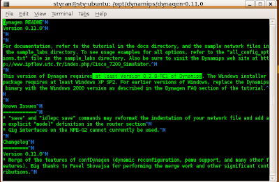
8) The README.txt file in this directory gives you the version of Dynamips required.

vi README.txt


The highlighted section above tells us to use atleast version 0.2.8-RC1 or higher of Dynamips.

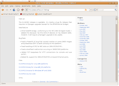
9) Goto Dynamips blog and wget the amd64 (64bit version)

http://www.ipflow.utc.fr/blog
/

Change back to /opt/dynamips directory

cd /opt/dynamips

sudo wget http://www.ipflow.utc.fr/dynamips/dynamips-0.2.8-RC2-amd64.bin

Note: Above file is the 64bit version of dynamips, since I am running it on Ubuntu 8.04 64bit

9) Change the permission of the downloaded file

sudo chmod 755
dynamips-0.2.8-RC2-amd64.bin

10) Create symbolic links for dynamips and dynagen

cd /usr/bin
sudo ln -s /opt/dynamips/
dynamips-0.2.8-RC2-amd64.bin dynamips
sudo ln -s /opt/dynamips/dynagen-0.11.0/dynagen dynaged

12) Create a directory for your IOS images
cd /opt/dynamips sudo mkdir images

13) Download the IOS images and place it in
/opt/dynamips/images directory
All ready to run DYNAMIPS!!!


1) Navigate to

cd /opt/dynamips/
dynagen-0.11.0/sample_labs/simple1

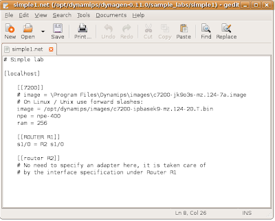
2) Edit simple1.net file

sudo gedit simple1.net


Specify the correct path of your images, in this case /opt/dynamips/images/XXXXXX.bin.
Also change RAM size as required by the IOS.


Save and Exit.


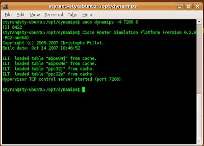
3) Run the Dynamips process

sudo dynamips -H 7200 &

4) Use dynagen to load simple1.net file

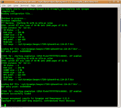
sudo dynagen simple1.net
5) At => prompt type ? for a list of options. List command will show the devices available as configured in the .net file.

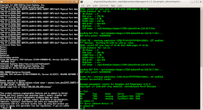
6) Telnet to a device.
Telnet R1

Note: You can also use your favorite programs such putty and telnet to localhost:2000 etc

In the next section, I'll discuss how to configure idlepc values so that your CPU is not on 100%, when you load several devices in your lab.

Saturday, September 20, 2008

New Notebook


I just got a Toshiba Satellite A300/U01 on Friday. The funny part is, I had made up mind on getting the A300/CO1 ($1799) . However, when I reached the store, I was told it was no longer in stock. But of course, they had the A300/U01 ($1899). I was about to leave thinking it was above my budget, anyway, I told the guy at the store, "The A300/U01 is a bit too expensive for me, if you could it give it for $1800, I'll take it". To my surprise, he agreed and the rest as you know is history. It will now provide me with the necessary computing power (mobility) and will act as a replacement to my existing Toshiba Satellite P10 (not so mobile :) ), which by the way has served me for the last 4 and 1/2 years now.

Study update

Well I have been so busy with work lately and that raises the question "Who isnt?". We recently upgraded our distribution switch, chucked the Nortel Baystack and replaced it with Cisco Cat-3550. It is now responsible for routing Inter VLAN traffic in our office.

The good part about the upgrade was eliminating all of the "router on a stick" configuration for many of VLANs in place. Apparently, it has also stopped our router (Cisco 2801) from crashing and rebooting frequently. We're also in progress of implementing our new monitoring system, i.e ZenOS. It will be a robust system, aiding in proactive monitoring to increase operational efficiency while combining the features of our existing monitoring tools.

As far as studies is concerned, I am on Chapter 19 reading getting a feel for MPLS, especially MPLS VPNs. We have MPLS VPNs (VRFs) implemented for a couple of our end customers. Last week, I also received my Routing TCP/IP Volume I book. I cant wait to dig into it.

Sunday, August 31, 2008

Recommended Books

I have started reading (1), I am yet to buy the rest, which I will as I complete (1).
Internetwork Expert provides a more complete recommended reading list. However, depending on your proficiency, you may choose to purchase those books covering concepts you need to understand further. I havent decided on which book I'd choose for MPLS.

The hard part ofcourse is reading, dedicating the necessary hours. It's definitely not easy preparing while having a full time job. However, if you're working in a related field you may be able to quickly absorb things (this is where your industry experience comes in handy).

Genesis

I am currently preparing for my CCIE (R&S). Unlike a lot of other networking professionals out there, I havent had a lot of industry experience, although I an beginning to absorb quite a lot in my current role.

The first question that came to my mind when I began preparing for the CCIE was, why should I even think about doing it now, when I havent had a lot of industry exposure. To me, its more like there is no right time because even with a lot of industry experience it still requires one to follow a structured approach. Chances are more likely that we're exposed to certain concepts more often than others. Please note that I am not downplaying the value of industry experience, all I striving for is to inspire those people who probably like me havent had a lot industry experience but have the drive and passion to go through what it takes to become one.

I have a good grasp of the concepts through my engineering background, certifications and I am continuing to build on it, which I believe is the first step. I'd like to quote Brian Dennis from Internetwork Expert "understand the technology", its more like know why you are doing what you are doing. Once you're thorough with your concepts, move onto practicing the technology through workbooks and crazy scenarios from your head.

In my next post, I'll go through the materials that I am using and will use in my preparation.